We are now required to collect sales tax in Florida, Iowa, New Jersey & Ohio. If you are tax exempt, please create an account and send us your sales tax exemption form before placing an order. MORE INFO
/Products/VFD's & Soft Starters/Teco-Westinghouse/A510 Heavy Duty Drives/460VAC/A510-4025-C3-UE Teco-Westinghouse 25HP Heavy Duty AC Drive, 460VAC

Product ID: A510-4025-C3-UE

A510-4025-C3-UE Teco-Westinghouse 25HP Heavy Duty AC Drive, 460VAC

MFG: TECO-Westinghouse
MFG Part Number: A510-4025-C3-UE

Selected accessories will also be added to cart
$1,679.40 / Each
Quantity:
380-480VAC 50/60Hz 3 Phase Input, 39 Amps, LCD, NEMA 1 IP20 Enclosure, B

Description

The A510 Heavy Duty AC Drive is an easily configured versatile drive product that will control all general applications such as fans, pumps, conveyors, and mixers. It comes standard with a simple to select preset application parameters for many commonly used applications.

Despite its simple and easy approach, the A510 is loaded with features to solve tough and demanding applications such as reciprocating pumps, compressors and high torque/ high inertia loads

Advanced algorithms allow the A510 to perform tight and precise speed control when coupled with encoder feedback on the motor being controlled.
Product Specifications

Manufacturer Teco-Westinghouse
Model A510-4025-C3-UE
Input Voltage 380-480VAC
50/60Hz
3 Phase
HP 25 HP (Constant Torque)
30 HP (Variable Torque)
Amps 39.0 Amps (Constant Torque)
44.0 Amps (Variable Torque)
Height 14.17 inches
360 mm
Width 10.43 inches
265 mm
Depth 8.86 inches
225 mm
Est. Weight 22.0 lbs
10.0 kg
Diagram B
Braking Transistor Built-In
Braking DC Link Reactor
Enclosure NEMA 1 (IP20) / F4

Applications

  • Compressors
  • Metals Processing: Industrial Saws, Punch Press and Screw and Bolt Manufacturing
  • Machine Tool Operations: Grinding, Milling and Lathes
  • Plastic and Rubber Process Machines: Extruders and Rubber Compounding
  • Cranes, Hoists and Materials Handling

Features

  • Selectable Control Modes:
    V/F Mode with constant and variable torque settings
    V/F Mode with PG encoder feedback
    Sensorless Vector
    Sensorless Vector with permanent magnet motors
    Closed Loop Vector
    Closed Loop Vector with Permanent Magnet Motors
    Sensorless vector control with dynamic control and rotational tuning
  • Attains High Torque Levels:
    200% Starting torque in sensorless vector modes
    200% Holding torque in closed-loop vector modes
  • Select matching application type for quick setting of parameter defaults
  • Advanced regenerative energy handling capabilities with overvoltage suppression
  • Extensive Monitoring and Display capabilities:
    Display over 40 different operating and status information variables
    Retains 4 most recent faults in a log
  • PLC functionality built-in
  • Advanced tuning/ motor matching capabilities
  • Pulse Width Modulation (PWM) technology
  • 32 Bit, 100 MHz processor for extremely fast response
  • Digital I/O:
    8 configurable digital inputs
    3 digital outputs
    Safety input contact for user’s interlock circuit
  • Analog I/O:
    2 analog inputs
    1 0-10VDC analog output
    0-10VDC/ 4-20mA output
  • Pulse I/O:
    1 pulse input channel capable of up to 32 kHz
    1 pulse output channel capable of up to 32 kHz
  • Removable I/O terminal strip

Operating Characteristics

Features

Control Modes V/F
V/F+PG
SLV
SV
PMSV
PMSLV
SLV2
Frequency Control Range 0.1Hz to 599.99Hz
Frequency Accuracy (Temperature Change) Digital references: ±0.01% (-10 to +40ºC)
Analog references: ±0.1% (25ºC ±10ºC)
Speed Control Accuracy ±0.1% (closed loop vector control)
±0.5% (sensorless vector mode)
Frequency Setting Resolution Digital references: 0.01Hz
Analog references: 0.06Hz/60Hz
Output Frequency Resolution 0.01Hz
Overload Tolerance rated output current 150%/1 min
200%/2sec (CT mode)
120%/1 min (VT mode)
factory setting of 150%/1 min
200%/2 sec
Frequency Setting Signal 0 to +10VDC
4 to 20mA
-10VDC to +10VDC
pulse–type frequency command
Acceleration / Deceleration Time 0.0 to 6000.0 sec (separately set acceleration and deceleration times)
Voltage and frequency characteristics Can set custom V/ F-curve based on parameters
Braking torque Approxiamtely 20%
Main control functions Auto tuning
shaft lock
torque control
position control
droop control
soft-switching in PWM
over-voltage protection
dynamic braking
speed search
frequency traversing
instantaneous power fault restart
PID control
automatic torque compensation
slip compensation
RS-485 communication MODBUS standard
speed feedback control
simple PLC functionality
2 sets of analog output
safety switch interlock
Additional control functions Record of elapsed power-up and operation times
4 most recent occurrences of faults and the most recent fault record
status
energy-saving function setting, single phasing protection
smart braking
DC braking
dwell
S-curve acceleration and deceleration
Up / Down operation
MODBUS communication type
scale pulse output
engineering unit display
Local/remote switching keys
SINK/ SOURCE input interface options
stall protection
Communication function RS-485 standard with built-in (MODBUS) (RJ45)
PLC function Built-in
EMI protection The added noise filter complies with EM61800-3, 460V; 215 HP or below can be built-in.
EMS protection Follows EN61800-3

Protection Features

Stall Protection Threshold current can be set (in acceleration or constant speed, it can be set separately. In deceleration, it can be set on or off )
Instantaneous Over Current (OC)
Output Short Circuit (SC)
nverter shuts off when the current exceeds 200% of the inverter related current.
Inverter Overload protection (OL2) Inverter rated current is 150%/1 min, at 200%/2 sec, inverter stops (CT type), carrier frequency factory setting is 8~2 kHz. At 120%/1 min, inverter stops (VT type), carrier frequency factory setting is 2 kHz.
Motor Overload (OL1) protection Electrical overload protection curve
Over Voltage (OV) When the main circuit DC voltage exceeds 410V (230V units)/ 820V (460V units), 1,050V (575V units)/ 1,230V (690V units), the drive faults out regardless of whether it is in run mode or stopped.
Under Voltage (UV) When the main circuit DC voltage is under 190V (230V units)/ 380V (460V units), 546V (575V units)/ 575V (690V units), the drive faults out regardless of whether it is in run mode or stopped. The DC voltage trigger level can be adjusted.
Automatic restart after instantaneous power fault Power fault exceeds 15 ms. This is programmable to 2 seconds.
Overheat protection (OH) By direct temperature detection in the unit
Ground Fault protection (GF) Uses current feedback for protection
Protection in charge state When main circuit DC voltage exceeds 50V, the “CHARGE” LED is on.
Output Phase Loss Protection (OPL) Automatically stops motor rotation and faults

Environmental Specifications

Location Indoor (protected from corrosive gases and dust)
Ambient temperature -10 to +40°C without de-rating (IP20/NEMA1)
-10 to +50°C (IP00)
with de-rating, its maximum operation temperature is 60°C
Storage temperature -20 to +70°C
Humidity 95%RH or less (no condensation)
Altitude Altitude of 1,000 m (3,300 ft) or lower
Vibration below 5.9 m/s2 (0.6G)

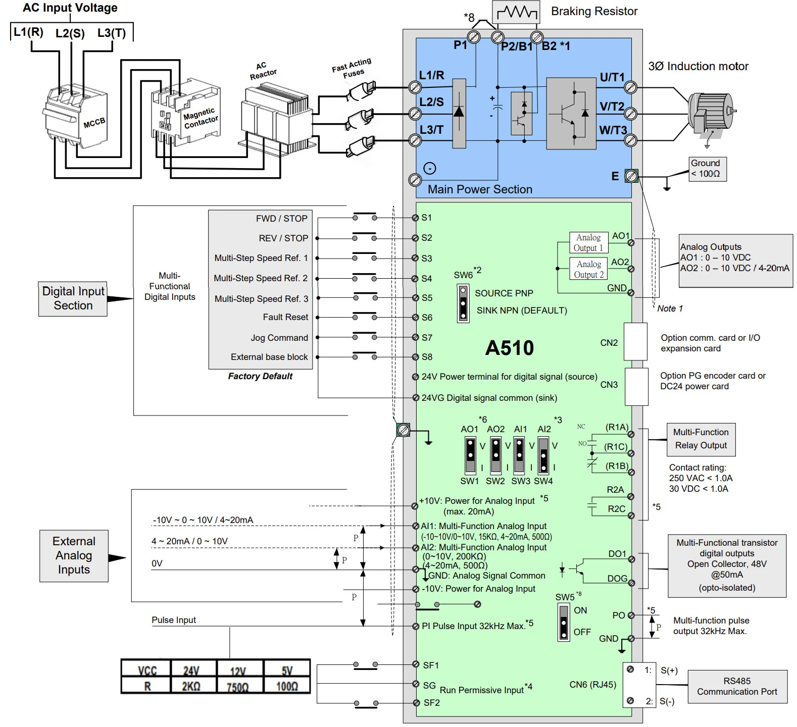
Connection Diagram

Teco-Westinghouse A510 UE Wiring Diamgram

Notes:

1: Models 230V 1 to 25HP and 460V 1 to 30HP or lower ratings have a built-in braking transistor. To use this braking transistor a braking resistor can be connected between B1 and B2.

2: Use SW6 to select between Sink (NPN, with 24VG common) or Source (PNP, with +24V common) for multi-function digital input terminals S1 to S8.

3: Use SW3/SW4 to switch between voltage (0 to 10V) and current (4 to 20mA) input for Multi-function analog input 2 (AI2). Besides please also check parameter 04-00 for proper setting.

4: Run Permissive input SF1 and SF2 is a normally closed input. This input should be closed to enable the inverter output. To activate this input remove the jumper wire between SF1/ SF2 and SG.

5: When using the open collector for pulse input, it doesn’t need resistance because of built-in pull-up resistance.

6: AO1/AO2 default setting is 0~+10V.

7: Both 230V class 50HP to 150HP and 460V class 100HP to 425HP have built-in DC reactors.

8: It need turn on the switch for the terminal resistor RS485 in the last inverter when many inverters in parallel connection.

Links